Remote-processing RPC-220 Manuel d'utilisateur Page 21
- Page / 47
- Table des matières
- MARQUE LIVRES
- TRADEMARKS 1
- NOTICE TO USER 1
- FCC NOTICE 1
- TABLE OF CONTENTS 2
- OVERVIEW SECTION 1 4
- SETUP AND OPERATION SECTION 2 10
- INTRODUCTION 12
- OPERATING MODES 12
- MEMORY MAPS 12
- ACCESSING I/O AND RAM 13
- MONITOR ROM 13
- MONITOR COMMANDS 14
- SAVING YOUR PROGRAM TO FLASH 18
- WRITING CODE FOR UPDATES 18
- WRITING FOR C 19
- USING DEMONSTRATION PROGRAMS 19
- PROGRAMS LARGER THAN 32K 19
- APPLICATION PROGRAMS 20
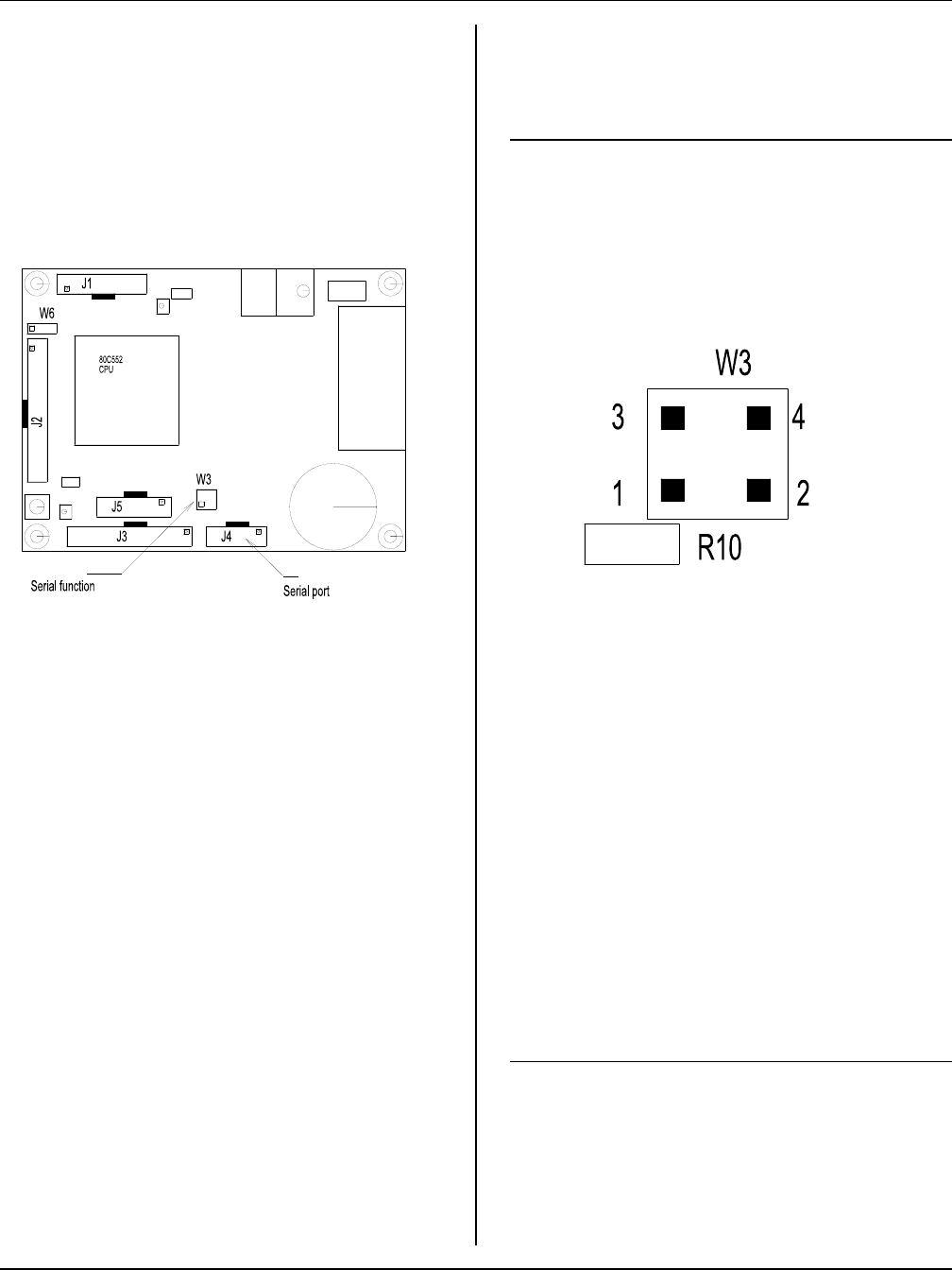
- SERIAL PORTS SECTION 4 21
- RAM SECTION 5 23
- DIGITAL LINES SECTION 6 24
- REAL TIME CLOCK SECTION 7 26
- COUNTER/TIMERS SECTION 8 30
- WATCHDOG TIMER SECTION 9 32
- APPLICATION PROGRAM 33
- ANALOG INPUT SECTION 11 34
- PROGRAMMING PWM 38
- ANALOG OUTPUTS 38
- PIN OUTS AND REGISTER 39
- INFORMATION 39
- DISPLAY PORT SECTION 13 40
- EXPANSION PORT SECTION 14 43
- MECHANICAL 46
- SHOCK AND VIBRATION 46
- MOUNTING TO A MOTHER BOARD 46
Produits connexes et manuels pour Ordinateurs Remote-processing RPC-220
 (44 pages)
© 2020, manymanuals.fr. Tous droits réservés | 0.924 s |
 Manymanuals.com
 Manymanuals.de
 Manymanuals.fr
 Manymanuals.it
 Manymanuals.pl
 Manymanuals.cz
 Manymanuals.es
 Manymanuals-pt.com
Commentaires sur ces manuels